
Photo V-Carve Toolpath
The Photo V-Carve toolpath uses the V-bit to etch a copy of the selected bitmap picture into the surface of your material.
Watch this video to see this in action:
 Preparing the bitmap
Section titled “ Preparing the bitmap”This strategy requires a source bitmap image or photograph to be selected in the 2D View.
Your source bitmap can be edited in a number of ways before using this form to create your Photo V-Carve toolpath. You can use the Crop Bitmap command to trim a bitmap to a vector outline. This will allow you to remove any parts of a bitmap that you do not require.
The Edit Picture tool can also be used prior to creating the toolpath in order to adjust many important aspects of your image - such as brightness and contrast. In addition it can be used to add a feathered border the image. For the best results you should use this tool to highlight and accentuate out the important details of your image before creating your toolpath.
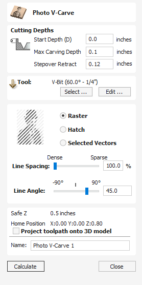
The fields on the form are as follows.
Cutting Depths
Section titled “ Cutting Depths” Start Depth (D)
Section titled “ Start Depth (D)”This specifies the depth at which the Photo V-Carving toolpath is calculated, allowing Photo V-Carving to be machined inside a pocket region. When cutting directly into the surface of a job the Start Depth will usually be 0.0. If the Photo V-Carving is going to be machined into the bottom of a pocket or stepped region, the depth of the pocket / step must be entered. For example, to carve or engrave into the bottom of a 0.5 inch deep pocket, the Start Depth = 0.5 inches
Max Carving Depth
Section titled “ Max Carving Depth”Max carving depth is the maximum depth the tool will cut into the material. It also impacts the number of lines that can be carved into a job at a specific size.
Stepover Retract
Section titled “ Stepover Retract”This parameter specifies how much the tool will retract before moving to the next line. This should be set to a value high enough, to allow tool to move safely to start of the adjacent line, but as low as possible to avoid slowing down machining.
Clicking the Select button opens the Tool Database from which the required VCarving or Engraving Tool can be selected. See the section on the Tool Database for more information on this.
Clicking the Edit button opens the Edit Tool form which allows the cutting parameters for the selected tool to be modified, without changing the master information in the database.
Strategy Settings
Section titled “ Strategy Settings” Raster
Section titled “ Raster”Selecting this option will generate a single set of parallel lines, or stripes, across your selected image.
This option will create two sets of parallel lines at 90 degrees from one another. This strategy will generally produce a denser image reproduction, but will typically take twice as long to etch.
Selected Vectors
Section titled “ Selected Vectors”Selecting this option will generate toolpath along the selected vectors. This is an advanced option that allows to produce special effects, but requires more time to set-up. You can use the Vector Texture tool to generate the vectors for use here.
Line Spacing
Section titled “ Line Spacing”This slider adjusts the gap between the raster stripes - tight striping produces a denser image reproduction, but will take a lot longer to etch. The line spacing is expressed in percentage of the tool width at maximum carving depth .
At 100% the line spacing is calculated to create a ‘knife edge’ ridge in the deepest regions of the design - no flat left on the material surface. This is the maximum definition / resolution based on the specified Depth.
Increasing the Line Spacing, reduces the number of lines and increase the width of the flat regions on the material surface.
Line Angle
Section titled “ Line Angle”Adjust this slider to change the angle of the stripes or hatching used to etch the image. Zero degrees will produce horizontal stripes and ninety degrees, vertical.
Position and Selection Properties
Section titled “ Position and Selection Properties” Safe Z
Section titled “ Safe Z”The height above the job at which it is safe to move the cutter at rapid / max feed rate. This dimension can be changed by opening the Material Setup form.
Home Position
Section titled “ Home Position”Position from and to that the tool will travel before and after machining. This dimension can be changed by opening the Material Setup form.
Project toolpath onto 3D Model
Section titled “ Project toolpath onto 3D Model”This option is only available if a 3D model has been defined. If this option is checked, ✓ after the toolpath has been calculated, it will be projected (or ‘dropped’) down in Z onto the surface of the 3D model. The depth of the original toolpath below the surface of the material will be used as the projected depth below the surface of the model.
Note:
When a toolpath is projected onto the 3D model, its depth is limited so that it does not exceed the bottom of the material.
The name of the toolpath can be entered or the default name can be used.