
Laser Cut And Fill
Note
The Laser Module is available as a paid-for add-on to the software. The features are not included in your software by default. To find out more about the Laser Module, please go to https://vectric.com/laser-module
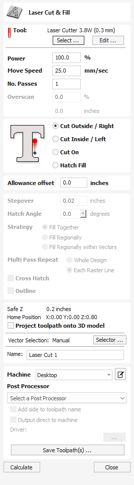
Laser Cut - Fill is used for cutting out shapes or marking areas.
Cut-outs can take into account the kerf, or width, of the laser beam to maintain the precise internal or external size the selected vector shapes. Shapes can also be filled with stripes or hatching to create simple shading effects.
 Tool Selection
Section titled “ Tool Selection” Select Tool
Section titled “ Select Tool”This button opens your database of previously stored laser settings for different jobs and materials. When a setting is selected fromt the database it will be used to populate the key fields in this section. You can subsequenlty modify these values when calculating the laser toolpath. Modifying the settings on this form will not alter the original stored settings within your database.
This value sets the proportion of the maximum laser power from your machines that will be used for this tool path.
Move Speed
Section titled “ Move Speed”This specifies the maximum speed that your machine will move during cutting or engraving moves. The units are determined by the database setting that was originally selected.
No. Passes
Section titled “ No. Passes”The machine can repeat a tool path several times to cut through thicker material. This value sets the maximum depth the machine will attempt to cut with each pass to achieve the final Cut Depth.
Overscan
Section titled “ Overscan”Overscan allows the user to have the laser pass beyond the edge of the lasered area, to account for deceleration of the machine which would otherwise result in a darker edge to the laser burn. Overscan is machine dependant and the user will need to run some test images to identify how much overscan to use on their machine at a given feedrate to eliminate overburn at the edges of the lasered area.
Strategy
Section titled “ Strategy”Based on the selected vector shapes in your drawing, this toolpath offers four distinct strategies.
Cut Outside / Right
Section titled “ Cut Outside / Right”Selecting this option will run the laser around the outside of your selected vector shapes (or along their right-hand edge, if they are open vectors). The actual path of the laser is automatically offset from the orginal shape according to the kerf width of the laser. As a result, the external dimensions of the resulting physical part precisely match the size of the original vector drawing. This strategy should be used for cutting out shapes to precisely the correct dimensions.
Cut Inside / Left
Section titled “ Cut Inside / Left”This option will run the laser around the inside (or left-hand edge) of your selected vector shapes, allowing for the kerf of the laser. This strategy is typically used for cutting holes, slots or sockets where the remaining recess has precisely the same dimensions as the original selected vector drawing.
Cut On
Section titled “ Cut On”This option will run the center of the laser beam along the selected vector. No offsetting or kerf compensation is required.
Hatch Fill
Section titled “ Hatch Fill”This is a marking or ‘shading’ strategy which profiles along the selected vectors and then fills-in the shapes with stripes. When this option is selected the additional Stepover, Hatch Angle and Cross Hatch options will also become enabled - see below for more information on these.
Allowance
Section titled “ Allowance”This setting allows you to add an additional offset for the Cut Outside, Cut Inside strategies without adjusting the laser kerf settings and can be useful for easing or tightening the fit of shapes resulting from these cuts.
Note
This option is not applicable to the Cut On or Hatch Fill strategies and will be disabled if they are selected.
Stepover
Section titled “ Stepover”When creating hatch fills, this option determines the spacing between the hatch lines. It is only available when the Hatch Fill strategy is selected.
Hatch Angle
Section titled “ Hatch Angle”When the Hatch Fill strategy is selected, this option determines the angle of the hatching lines used.
Fill Together / Fill Regionally
Section titled “ Fill Together / Fill Regionally”These options will change how areas separated by spaces are treated. In the example of the word “Test” with Fill Together selected the letters will be treated as one whole space to be filled whereas with Fill Regionally each letter will be treated separately as its own individual region.
Cross Hatch
Section titled “ Cross Hatch”Checking this option will create a cross hatch fill instead of a single set of lines.
Outline
Section titled “ Outline”Selecting this option will then create a defined outline around a chose vector. If unchecked there may be gaps around the edges if the stepover is large enough whereas when checked an outline passing around the outside will appear.
Position and Selection Properties
Section titled “ Position and Selection Properties” Safe Z
Section titled “ Safe Z”The height above the job at which it is safe to move the cutter at rapid / max feed rate. This dimension can be changed by opening the Material Setup form.
Home Position
Section titled “ Home Position”Position from and to that the tool will travel before and after machining. This dimension can be changed by opening the Material Setup form.
Project toolpath onto 3D Model
Section titled “ Project toolpath onto 3D Model”This option is only available if a 3D model has been defined. If this option is checked, ✓ after the toolpath has been calculated, it will be projected (or ‘dropped’) down in Z onto the surface of the 3D model. The depth of the original toolpath below the surface of the material will be used as the projected depth below the surface of the model.
Note:
When a toolpath is projected onto the 3D model, its depth is limited so that it does not exceed the bottom of the material.
Vector Selection
Section titled “ Vector Selection”This area of the toolpath page allows you to automatically select vectors to machine using the vector’s properties or position. It is also the method by which you can create Toolpath Templates to re-use your toolpath settings on similar projects in the future. For more information, see the sections Vector Selector and Advanced Toolpath Templates.
The name of the toolpath can be entered or the default name can be used.
Immediate Output
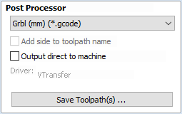
Section titled “ Immediate Output”Once calculated, your toolpath is stored in the central Toolpath Tree and can be saved, edited or output to your machine at anytime using the Save Toolpaths command. In addition though, this form also includes a convenient Immediate Output section that allows you to save or send the most recently calculated toolpath directly from this form without having to close it.
Post Processor
Section titled “ Post Processor”Use this drop-down list to select the post-processor for your machine.
Add side to toolpath name
Section titled “ Add side to toolpath name”If you are creating aligned toolpaths for a two-sided part, this option automatically adds the side name to the toolpath name as it is saved or exported to help keep your toolpaths organised.
Output direct to machine
Section titled “ Output direct to machine”If your post-processor supports direct access to your cnc machine (including machines supported by VTransfer), this option will be available. Selecting this option will bypass saving the toolpath to disk and instead send it straight to the direct output driver.