Nest Parts
The Nesting tool will automatically fit vector shapes within the user defined area in the most efficient way it can calculate (based on the user defined parameters). By default the area the vectors will be fitted is the current Job Size but it is also possible to select a vector as the nesting area. This is a powerful way to optimize material usage and increase toolpath efficiency when laying out and cutting a number of shapes.
Watch this video to see this in action:
 Object Selection
Section titled “ Object Selection”The Nesting tool allows you to select closed vectors, text, components and open vectors that are contained within closed ones.
Once selected the objects will form parts, with part outer boundary highlighted with a thicker line.
The basis for forming parts is overlapping. If selected object contains another or overlaps with it they will be considered the same part.
Tool and Clearance Settings
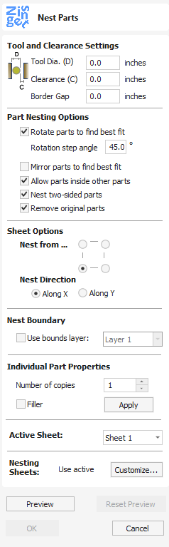
Section titled “ Tool and Clearance Settings”The settings in this section of the form will determine the spacing which will be left between each of the nested vectors and also control how close they are to the edge of your nesting area.
Tool Dia. (D)
Section titled “ Tool Dia. (D)”Enter the diameter of the tool that you will be using to Profile (cut-out) the vectors you are nesting. This is the minimum distance that will be left between shapes once they are nested.
Clearance (C)
Section titled “ Clearance (C)”The Clearance value will be combined with the specified Tool Diameter to create the final minimum spacing between the nested shapes. For example a Clearance of 0.05 inches combined with a Tool Diameter of 0.25 inches would create a minimum spacing gap of 0.3 inches (0.05 + 0.25 = 0.3).
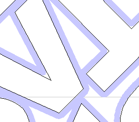
Clearance less than Tool Diameter
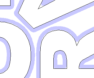
Clearance greater than Tool Diameter
Border Gap
Section titled “ Border Gap”The Border Gap value is applied to the edge of the area which is being used to nest the vectors into. It will be added to the Clearance value around the edge of this shape to create the minimum distance that parts will be nested in respect to the nesting boundary.

No Border Gap
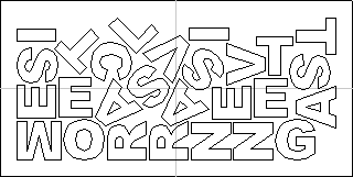
Border Gap
Part Nesting Options
Section titled “ Part Nesting Options”The options in this area of the form will all directly affect how many parts or how efficiently it is possible for the software to fit shapes into the defined nesting area.
Rotate Parts to find best fit
Section titled “ Rotate Parts to find best fit”Checking ✓ this option will allow the software to rotate the selected vectors in order to try and better fit them. The increments of rotation the software will use is based on the Rotation step angle.
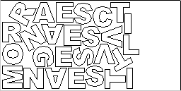
Rotate Parts Enabled
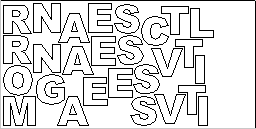
Rotate Parts Disabled
Mirror parts to find best fit
Section titled “ Mirror parts to find best fit”Checking ✓ this option will allow the nesting to mirror (flip) the vectors in order to try and more efficiently nest the selected shapes. This should only be checked ✓ if the direction the parts are cut in is not important.
Allow parts inside other parts
Section titled “ Allow parts inside other parts”Checking ✓ this option will allow the software to nest within the internal areas of shapes that have gaps in the middle.
When this option is active, the internal areas that will be considered in nesting will be highlighted.

Original

Parts Nested inside other parts
Nest two-sided parts
Section titled “ Nest two-sided parts”This option is only available for double-sided projects and allows nesting on both sides simultaneously. When this option is active, any visible objects on the other side will be included, if they intersect with objects selected on active side.
When using this mode it is recommended to perform selection on the side that contains cut-out contours.
When part is selected, the included vectors on the other side will be highlighted as can be seen below.
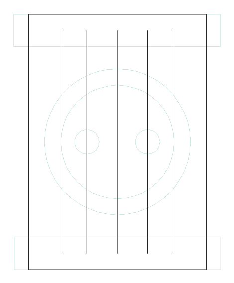
Double-sided part before selection
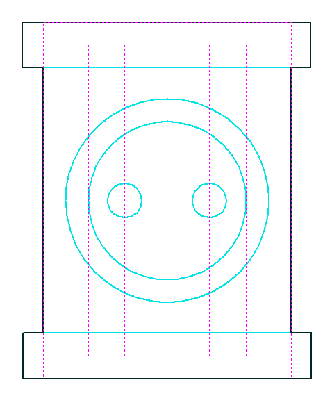
Double-sided part when selected
Remove original parts
Section titled “ Remove original parts”If this option is checked the original parts are removed in the nesting rather than duplicated in the nest.
Filler Part
Section titled “ Filler Part”Select the vector you wish to use as the Filler Part, tick the “Filler” Tick box and click Apply to set this. The Filler Part Vector will be marked with a Green asterisk (*)
When the Nesting preview is applied, any area not filled by other nesting parts will be filled with as many Filler parts as can be made to fit in the remaining Sheet space.
Sheet Options
Section titled “ Sheet Options” Nest From
Section titled “ Nest From”This area of the form is used to define which corner the nesting will start in. There are four options which can be selected from the options in the form.
Nest Direction
Section titled “ Nest Direction”The options in this area of the form are used to select how the parts will progress as they are positioned within the sheet. The best way to think of this (for the purposes of this section) is that they ‘pour’ out of the selected corner filling the sheet in one axis then advancing along the other defined axis (X or Y) .
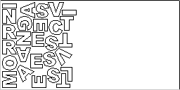
Along X
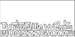
Along Y
Individual Part Properties
Section titled “ Individual Part Properties”If you want more than one incidence of a particular item then select it from the 2D view. In the box where it says Number of Copies enter as many copies as you want and hit Apply and the selected vectors will be marked with a green number indicating how many copies of that item will be made when they are nested. Different shapes or groups of shapes can be assigned different numbers of copies. To stop an item being copied multiple times just set the Number of Copies back to 1 and click Apply.
Nest boundary
Section titled “ Nest boundary”A nesting boundary can be specified by choosing a layer whose vectors will represent the nesting boundary. Multiple vectors can be used, allowing holes and areas to be excluded from the nesting to be represented. The nesting process will try to place the nested objects inside the vectors of the boundary layer.
Active Sheet
Section titled “ Active Sheet”This option lets you choose which Sheet of vectors is currently active, either for editing or applying toolpaths onto.
Nesting Sheets
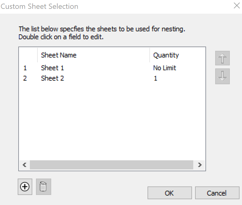
Section titled “ Nesting Sheets”For more complicated nesting requirements it is possible to define how the nested parts are placed on to existing sheets and how new copies of existing sheets might be created to accomodate more parts. To edit the default setting click on the Customize button.
The Custom Sheet Selection form show the list of sheets we have to nest on to.